By W. R. Dearman (Auth.)
Engineering and environmental geology mapping is worried with representing the uppermost few tens of metres, enormously extra, of the varied rocks and soils comprising the Earth's floor in a way that may be simply understood through geologists and non-geological experts, reminiscent of planners. Ease of interpretation of 3-dimensional truth from a two-dimensional map or plan is paramount if the maps are for use to top virtue. Having validated the fundamental ideas of engineering geological mapping, assistance is given on how one can make such maps and what to place on them. elements are of specific value. One is the outline of earth fabrics in phrases that show most likely engineering homes and behavior; nationwide and foreign criteria were constructed for this objective. the opposite is supporting or simplifying the translation of the map; the stripe process and the extra basic zoning process departing from the normal geological method of mapping, express how this is often performed. the foundations are illustrated via examples at small scale, terrain assessment at medium scales, and concrete geology and development websites on the biggest scales. Environmental elements contain threat and probability overview, and land and water administration. desktop aided mapping offers and fascinating prospect for the longer term
Read Online or Download Engineering Geological Mapping PDF
Similar mining books
Hardrock tunnel boring machines
This e-book covers the basics of tunneling computing device expertise: drilling, tunneling, waste removing and securing. It treats equipment of rock class for the equipment involved in addition to criminal concerns, utilizing a variety of instance tasks to mirror the kingdom of expertise, in addition to complex situations and strategies.
Handbook of Flotation Reagents: Chemistry, Theory and Practice: Volume 1: Flotation of Sulfide Ores
Guide of Flotation Reagents: Chemistry, concept and perform is a condensed type of the basic wisdom of chemical reagents general in flotation and is addressed to the researchers and plant metallurgists who hire those reagents. such as 3 specified components: 1) offers unique description of the chemistry utilized in mineral processing undefined; 2) describes theoretical elements of the motion of flotation reagents three) offers info at the use of reagents in over a hundred working crops treating Cu, Cu/Zn, Cu/Pb, Zn, Pb/Zn/Ag, Cu/Ni and Ni ores.
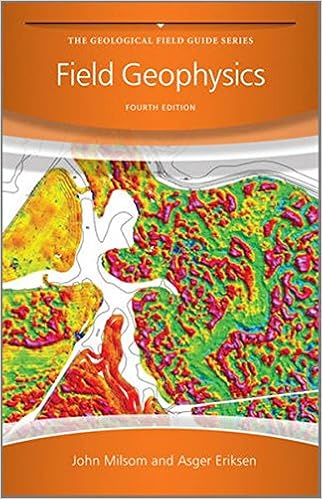
Preface to the 1st variation. Preface to the second one variation. Preface to the 3rd variation. Preface to the Fourth variation. 1 advent. 1. 1 What Geophysics Measures. 1. 2 Fields. 1. three Geophysical Survey layout. 1. four Geophysical Fieldwork. 1. five Geophysical information. 1. 6 Bases and Base Networks.
- New Frontiers in Mining Complex Patterns: First International Workshop, NFMCP 2012, Held in Conjunction with ECML/PKDD 2012, Bristol, UK, September 24, 2012, Rivesed Selected Papers
- Managed Pressure Drilling. Modeling, Strategy and Planning
- Georgius Agricola
- Ground Support in Mining and Underground Construction: Proceedings of the Fifth International Symposium on Ground
Additional resources for Engineering Geological Mapping
Example text
Systematic joints may be present in one or more sets, and influence rock mass and block size. Block size and shape The spacing of discontinuities may be described with reference to the size and shape of rock blocks bounded by discontinuities and by the relative persistence of diñ'erent discontinuity sets. 8. 7 Typical profiles for the roughness categories for discontinuity surfaces (After ISRM 1977, Fig. 17) The stage of weathering of the rock material may be described in terms of degree o f discoloration, decomposition and disintegration from the fresh state (Dearman, 1974, 1976).
9. 9 Aperture of discontinuity surfaces Term Aperture (mm) Very wide Wide Moderately wide Moderately narrow Narrow Very narrow Over 200 60-200 20-60 6-20 2^6 0-2 Tight Zero • Polyhedral blocks. Irregular discontinuities without arrangement into distinct sets, and of small persistence. • Tabular blocks. One dominant set of parallel discontinuities ( 1 ) , for example bedding planes, with other non-continuous joints; thickness of blocks much less than length or width. • Prismatic blocks. T w o dominant sets o f discontinuities (1 and 2), approximately orthogonal and parallel, with a third irregular set; thickness o f blocks much less than length or width.
This method of plotting can handle planes with any attitude, and the data can be plotted by computer. In many situations rock mechanicians, in particular, prefer to plot planar orientation in terms o f dip direction and dip amount. What has been plotted should always be stated, otherwise gross errors of interpretation can arise. Either the complete contoured diagram, or a diagram showing just the plots, may be drawn on the map or plan. Spacing This term refers to the mean or modal spacing of a set of joints, that is the perpendicular distance between adjac ent discontinuities.


